


Time relay RVO-26M with delay after removing the power supply
  |
|
RVO-26M ACDC24-240V UHL2
|
3242.00 руб. с НДС
|
|
|
RVO-26M ACDC24-240V UHL4
|
2349.00 руб. с НДС
|
|
-
The time delay after switching off the supply voltage: 0,1-9,9s; 1-99s; 0,1-9,9min; 1-99min
-
Setting time delay by using two turning decade switches
-
4 operation diagrams
-
1 switching group contacts 5A/250V
-
Indicator of availability of power
-
Width of the case is 13mm
PURPOSE OF THE RELAY
Time relay RVO-26M is designed to forming delay at off built-in relay after removal of the supply voltage (operation diagram 26 and 27) or for testing fixed time delay after turning on supply voltage.
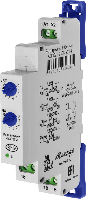
DESIGN OF THE RELAY
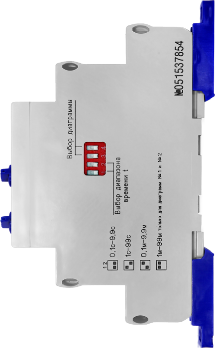
Relay is produced in a plastic case with a unified front connection wires power and switched circuits. Mounting is carried out on a DIN rail width 35mm (GOST R IEC 60715-2003) or on a smooth surface. To set on a smooth surface, you need to push locks. Terminal design provides robust clamp wires up to 2,5mm2. On the front panel there are: two turning switches to set the delay time t (setting value units 0-9 and 0-9 tens), green LED power-on «U». On the side surface is located DIP-switch to set a time range (switch 1, 2) and operation diagrams (switch 3, 4).
OPERATION OF THE RELAY
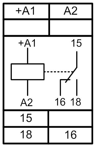
Operation diagram and time delay range is selected by DIP-switch, located on the side surface. For each diagram, you can choose one of three (0,1s-9,9s, 1s-99s, 0,1min-9,9min) delay time ranges, advanced to diagrams 1 and 2 has a fourth range 1-99min. The required time delay t is determined by multiplying the numerical value set on the switches "units" and "tens", a multiplier of the selected range on the DIP-switch. The supply voltage is applied to the terminals "+ A1" and "A2". Circuit of connection of relays is shown below and on the case of device.
WARNING: In the design of the product applied polarized electromagnetic relay with two stable states. Single blows during transport can result in spontaneous switch contacts. Wrong position of the contacts before the first switching on the relay does not indicate defects in the relay. The first time the original (OFF) state of the contacts is restored. Do not install the relay in an area of high vibration, or near devices which cause vibrations when activated (eg, high-power actuators, etc.).
| A parameter | Unit | RVO-26M | |
|
Supply voltage
|
V
|
АСDC24-240
|
|
|
Range of the delays time
|
0,1-9,9s, 1-99s, 0,1-9,9min, 1-99min (only for 1, 2 operation diagrams) | ||
|
Deviation of counting time delay, not more
|
%
|
5
|
|
|
A time of prior staying of relay at power supply voltage for ensure time delay with a given accuracy
|
s
|
1
|
|
|
Availability time (switching on relay after power)
|
s
|
0,5
|
|
|
Maximum switching voltage
|
V
|
400
|
|
|
Maximum switching current: AC250V 50Hz (AC1)/DC30V (DC1)
|
A
|
5
|
|
|
Maximum switching power: АС250V 50Hz (АС1)/DC30V (DC1)
|
VA/W
|
1250/150
|
|
|
The maximum voltage between the power supply circuits and relay contacts
|
V
|
АС2000 (50Hz - 1min)
|
|
|
Mechanical endurance, not less
|
cycles
|
10х106
|
|
|
Electrical endurance, not less
|
cycles
|
100000
|
|
|
Quantity and type of contacts
|
|
1 switching group
|
|
|
Operating temperature range(different versions)
|
0C
|
-25…+55 (UHL4)
-40…+55 (UHL2)
|
|
|
Storage temperature
|
0С
|
-40...+70
|
|
| Immunity to interference from bursts in accordance with GOST R 51317.4.4-99 (IEC/EN 61000-4-4) | level 3 (2kV/5kHz) | ||
| Immunity to interference over voltage in accordance with GOST R 51317.4.5-99 (IEC/EN 61000-4-5) | level 3 (2kV +А1-А2) | ||
|
Climatic modification and placement category by GOST 15150-69(non-condensing)
|
UHL4 or UHL2 | ||
|
The degree's protection at case/terminals according to by GOST 14254-96
|
IP40/IP20 | ||
|
The degree of pollution in accordance with GOST 9920-89
|
2 | ||
|
Relative humidity of air
|
%
|
up to 80 (at 25°C)
|
|
|
Height above sea level
|
m
|
till 2000
|
|
|
Operating position in space
|
|
artbitrary
|
|
|
Mode
|
|
round the clock
|
|
|
Dimensions
|
mm
|
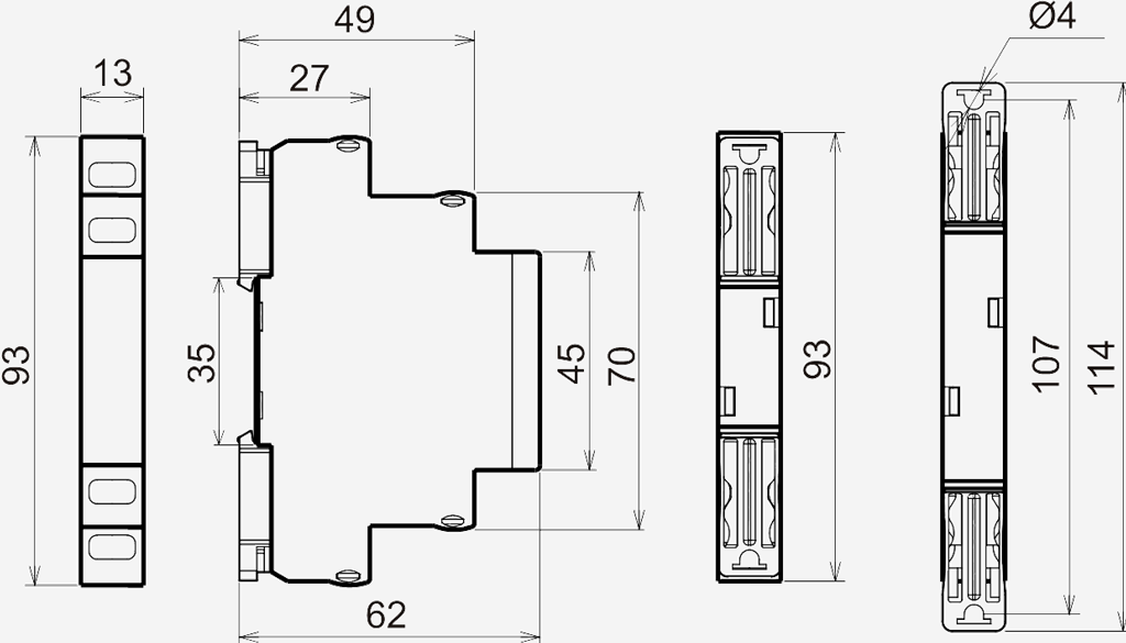
13х93х62
|
|
|
Weight
|
kg
|
0,056
|
|
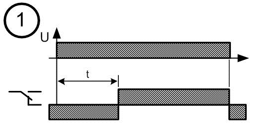
DIAGRAMS OF OPERATING THE RELAY
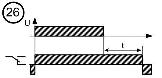 |
Delay relay operation after power is removed. The relay switches at the same time with applying power. Disabling the relay going after a specified time after the removal of the supply voltage. Time counting is interrupted when the power is turned back and resumed after its removal.
|
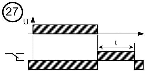 |
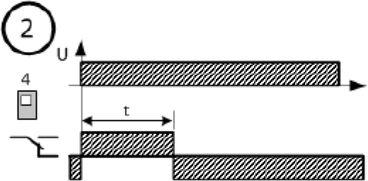
Delay relay operation after power is removed. The relay is turned on at the same time power off. relay off after a preset time. When reconnecting the power supply is interrupted the countdown and relay is going off. After the power is turned off the countdown starts again.
|
 |
The counting the set time begins when power is applied, after which the relay switches (switch-on delay). It is turned off, when the power is off.
|
 |
The relay is turned on simultaneously with power supply. Disabling the relay occurs after the set time counting (tripping delay).
|
CIRCUIT CONNECTION
DIMENSIONS OF THE RELAY
|
Title
|
Order code |
File to download
(manual)
|
File date
|
|
RVO-26M ACDC24-240V UHL2
|
4640016936878
|
02v.07.2015
|
|
|
RVO-26M ACDC24-240V UHL4
|
4640016936861
|
 Download
Английский